CARDIAC Simulation using PC/370 - Part 1
CARDIAC Simulation - Part 1 - Introduction to CARDIAC
CARDIAC Simulation - Part 2 - Primary Logic/Architecture
CARDIAC Simulation - Part 3 - Memory Design / Management
CARDIAC Simulation - Part 4 - CARDIAC Instruction Set Processing
CARDIAC stands for "CARDboard Illustrative Aid to Computation" - a learning aid to illustrate how computers function. Created in the 1960's by David Hagelbarger at Bell Labs. My daughter's computer class at Drexel focused on this recently to demonstrate simple concepts such as machine code, assembling source to object, etc. It's based on a memory architecture of 100 cells (0 thru 99) & some internal registers (a program counter & a single accumulator area). There are 10 operation codes (0 thru 9) that control the behavior & flow of the program. Cell values are generally 3 digits & represent either a value or machine code (or both). Primitive but very interesting!
More information on CARDIAC - Click Here
At first it appears very abstract, especially when looking at object code through the simulator. When my daughter asked for some guidance I browsed the material & created some code on scrap paper. Then I told her "I'm going to create my own simulator"!

Above: My CARDIAC PC/370 Simulator after reading all input values. Perfect!
Over Halloween weekend I was able to design, develop & successfully test my PC/370 CARDIAC Simulator. Every move matched the online simulator from my daughter's class. With the exception of some necessary GUI design differences all cells & logic flow was adhered to in sync with each other. The asterisk (*) marks the current location of the Program Counter.

Above: The online simulator used in my daughter's class.
The CARDIAC Instruction set. A 2 digit operand is specified after each 1 digit operation code to form the full instruction. The operands generally represent a cell address with the exception being SFT.
Opcode Mnemonic Operation
====== ======== ===================================================
0 INP Read a card into memory
1 CLA Clear accumulator and add from memory (load)
2 ADD Add from memory to accumulator
3 TAC Test accumulator and jump if negative
4 SFT Shift accumulator
5 OUT Write memory location to output card
6 STO Store accumulator to memory
7 SUB Subtract memory from accumulator
8 JMP Jump and save PC
9 HRS Halt and reset
====== ======== ===================================================
CARDIAC Source Assembly Code
The CARDIAC Simulator is based on the 3-digit object code (and values) that are placed in the memory locations 00 thru 99. Once the source assembly code is written it is meticulously translated into the object code format. This is done by hand but it wouldn't be too difficult to create a source code assembler. Maybe my next fun task...
Below is a simple program I wrote that is used in the simulator examples. The source assembly section is on the right with labels, mnemonics, operands & comments. The left side has the resulting cell location & object code contents.
CELL OBJECT SOURCE ASSEMBLY CODE
==== | ====== | ============================================================
00 | 001 | DATA 001 ;Initialize Cell 00
04 | 000 | ctr DATA 000 ;Initialize Counter
05 | 000 | sum DATA 000 ;Initialize Sum
06 | 001 | one DATA 001 ;Set Static Variable 1
07 | 000 | num DATA 000 ;Initialize Input Number
10 | 007 | loop INP num ;Read/Store Input Value
11 | 107 | CLA num ;Load Accumulator with Value
12 | 315 | TAC print ;Exit Loop when Negative
13 | 861 | JMP xproc ;Perform xproc Subroutine
14 | 810 | JMP loop ;Loop for next Input Value
15 | 504 | print OUT ctr ;Display Record Count
16 | 505 | OUT sum ;Display Sum Total
17 | 900 | HRS 00 ;Halt/Reset Program (DONE)
60 | 000 | xsave DATA 000 ;Accumulator Save Area
61 | 660 | xproc STO xsave ;Store Accumulator Value
62 | 199 | CLA ret99 ;Retrieve Return Address
63 | 671 | STO xexit ;Push Return to Exit
64 | 105 | CLA sum ;Load Accumulator with Sum
65 | 207 | ADD num ;Add Input Value
66 | 605 | STO sum ;Store Accumulator to Sum
67 | 104 | CLA ctr ;Load Accumulator with Count
68 | 206 | ADD one ;Add 1 to Accumulator
69 | 604 | STO ctr ;Store Accumulator to Ctr
70 | 160 | CLA xsave ;Restore Accumulator Value
71 | 800 | xexit JMP 00 ;Return to Main Process
99 | 800 | ret99 DATA 800 ;Return Address Area (JPM)
==== | ====== | ============================================================
The source code label represents the cell location of the instruction or data value. In this example the DATA directives define initial values in cells 04 thru 07 (00 is a special holder) while the actual program code begins in cell 10 (this is a highly recommended standard). The first instruction is INP which reads from the input queue & places the value in the cell with label num (which is 07). The full opcode is 007 (0 for INP & 07 for cell 07).
The online CARDIAC simulator requires the user to type values into the Deck then click Load to populate the READER queue used by the INP instruction. All code must be typed into the cells by the user as well. In my PC/370 version I store the Code & Deck values in a file that is read & utilized without having to retype the code/data.
CARDIAC PC/370 Simulator in Action:
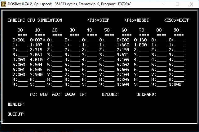
Above: My CARDIAC PC/370 Simulator in Action starting from Program Counter = 10.
The simulator begins in program counter 10 & executes each op code one by one - branching to other sections of the program via the JMP (jump) or TAC (Test Accumulator). The line to execute is tracked by the internal variable Program Counter (PC). This particular example loops through the input deck & calculates the count & sum of all records - then displays them via the OUT operation. Watch the asterisk (*) & the program counter (PC) track the current execution line.
This PC/370 CARDIAC Simulator Application was a simple little challenge... but fun.

That's a lot to absorb in a brief post. More to come on the PC/370 simulator version for CARDIAC. Stay tuned...